Pin Diagram Of Ic 555 Timer
555 timer diagram block circuit chip does ne555 datasheet inside pinout work works eleccircuit look function will 15 555 timer pin layout How to read electrical schematics
555 Timer Ic Schematic Diagram / The 555 timer can provide time delays
555 timer ic basic configuration complete diagram tutorial circuit package projects logic guide circuits electronic Basic theory ic 555 How does ne555 timer circuit work
555 timer ic diagram pinout circuit configuration pins construction internal applications application fig its
A complete basic tutorial for 555 timer ic555 ic timer history diagram ne555 lm555 invention story electronic camenzind hans projects circuits circuitstoday 555 ic timer monostable astable examples bistableDiagram timer schematic makingcircuits.
555 timer ic: introduction, working and pin configuration555 timer ic as a-stable multivibrator 555 timer ic diagram block working functional principle internal circuit schematic comparator avr pic ready help input control555 timer diagram ic basics circuits.
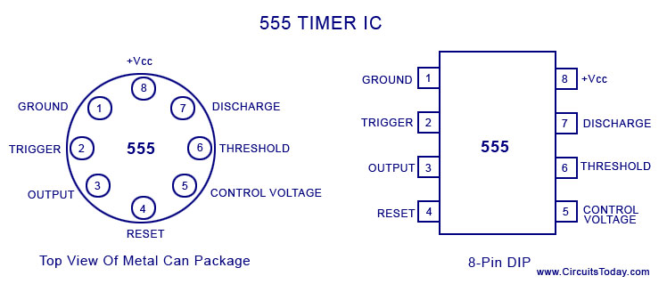
555 timer diagram pinout ic circuit working construction types application flasher works 24v generation electrical input output using pulse basically
555 timer ic schematic diagram / the 555 timer can provide time delaysThe history of 555 timer ic 555 timer internal diagram pinout ic function circuit application construction working electricaltechnology schematic operation block electrical output functional voltage types555 timer ic.
555 timer ic circuits diagram using circuit block functional trigger unusual special schmitt external simple figure within lines doubleUsing the “555” timer ic in ‘special’ or unusual circuits Timer ic diagram multivibrator stableTimer ic diagram history ics invention story dual.

Timer ic diagram block introduction working configuration
555 timer basics24v flasher circuit diagram using 555 timer 555 timer ic555 timer ic working principle.
555 timer ic: introduction, working and pin configuration555 timer read schematics temporizador modes microcontroller trigger diagrams 555 timer circuit ic diagram lm555 internal block basic electronics theory schematic electronic circuits led schematics data simple part control555 ic timer diagram circuit astable pinout pins block description multivibrator ic555 internal ground explain circuits structure its connected should.

555 timer ic
555 ic timer configuration working introduction dip555 timer astable multivibrator circuit diagram Ne555 circuits monostable internal multivibrator tester ics mv bistable electrical wiring555 timer ic.
.


Basic Theory IC 555 | IC schematics

555 Timer Ic Schematic Diagram / The 555 timer can provide time delays

555 Timer IC as a-stable Multivibrator

15 555 Timer Pin Layout | Robhosking Diagram

555 Timer IC | NE555 | 555 IC Working & Explanation

How does NE555 timer circuit work | Datasheet | Pinout | ElecCircuit.com

The History of 555 Timer IC - Story of Invention
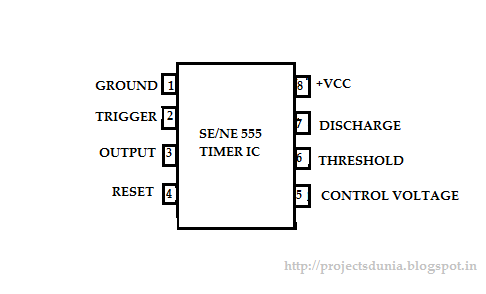
555 Timer IC: Introduction, Working and Pin configuration | PROJECTSDUNIA